
Industrial flanges are the critical connectors that hold piping systems together. They are not merely physical joints between pipes, valves, and pumps; they are the final line of defense ensuring zero leakage under extreme pressure and temperature fluctuations. Whether you are managing a high-pressure subsea oil line or a municipal water system, understanding the metallurgy, mechanical limits, and standardized procedures of flanges is the foundation of engineering safety.
Chapter 1: Metallurgy and the Logic of Material Selection
The choice of flange material is never a simple matter of cost. It is a calculated decision involving tensile strength, corrosion resistance, thermal expansion coefficients, and notch toughness. According to ASME B16.5, materials are categorized into "Material Groups," each with a unique pressure-temperature curve.
1.1 Carbon Steel: The Industrial Backbone
Carbon steel is the most widely specified material due to its exceptional strength and cost-efficiency.
-
ASTM A105: This is the primary grade for forged carbon steel piping components. It is designed for ambient and higher-temperature service. With a carbon content typically restricted to 0.35%, it ensures excellent weldability—a critical factor for field installations.
-
ASTM A350 LF2: For pipelines in Arctic regions or deep-burial applications, standard A105 can become brittle. LF2 carbon steel undergoes Charpy V-notch impact testing to ensure it remains ductile and resistant to fracture at temperatures as low as -46°C (-50°F).
1.2 Stainless Steel: Combating Corrosion and Contamination
In chemical processing and the food industry, corrosion is the primary enemy.
-
304/304L: Containing 18% Chromium and 8% Nickel, this grade offers excellent oxidation resistance and is the standard for general corrosive service.
-
316/316L: The addition of 2-3% Molybdenum gives this grade a high Pitting Resistance Equivalent Number (PREN), making it essential for chloride-rich environments like offshore oil rigs and pharmaceutical lines.
1.3 Alloy Steel and Superalloys
For power plants or refineries operating above 500°C (932°F):
-
ASTM A182 F11/F22: These chrome-moly alloy steels are engineered for high creep strength, preventing the metal from permanently deforming under sustained high-temperature stress.
-
Nickel Alloys (e.g., Inconel 625): Used in "Sour Service" (high H2S) or extremely acidic environments where standard steels would fail within days.
Chapter 2: The Dynamics of Pressure Classes and P-T Ratings
A flange's "Pressure Class" is a non-dimensional rating (Class 150, 300, 600, 900, 1500, and 2500) that governs its physical dimensions and pressure capacity.
2.1 The Pressure-Temperature (P-T) Relationship
A common misconception is that a Class 150 flange is rated for exactly 150 PSI. In reality, the rating is a dynamic curve. For an ASTM A105 Class 150 flange:
-
At 38°C (100°F), the maximum allowable working pressure (MAWP) is 285 psig (1.96 MPa).
-
At 260°C (500°F), the rating drops to 170 psig.
-
At 425°C (800°F), the rating plummets to just 80 psig.
This relationship can be understood through the simplified hydrostatic formula:
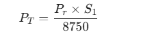
Chapter 3: Structural Varieties and Application Engineering
The geometry of a flange dictates how it handles stress. Different designs are used to manage vibration, thermal cycling, and axial loads.
3.1 Weld Neck Flange (WN)
The Weld Neck features a long tapered hub that is butt-welded to the pipe. This design provides superior stress distribution and reduces turbulence. It is the only choice for high-pressure, high-temperature, or cryogenic cyclic services.
3.2 Slip-on Flange (SO)
The pipe slips inside the flange and is welded both inside and out with fillet welds. While easier to align and lower in initial cost, its fatigue life is approximately one-third that of a Weld Neck flange under high-stress conditions.
3.3 Blind Flange (BL)
A solid disk used to seal the end of a system.
-
Case Study: The Blind Flange FF 2.5" #150 A105 Sch40 is a staple in waterworks. Because a blind flange must resist the full end-load of the pipe pressure, its thickness is often greater than other flanges in the same class.
3.4 Specialized Solutions: Split Flanges
For emergency repairs where a pipe cannot be cut, a Split Flange allows the technician to wrap the flange around an existing line. This dramatically reduces downtime in critical maintenance scenarios.
Chapter 4: Precision Measurement and Dimensional Standards
When replacing aged components or sourcing for international projects, precise measurement is the only way to mitigate risk. All measurements must adhere to ASME B16.5 tolerances.
4.1 Critical Measurement Parameters
-
Outside Diameter (OD): The total width of the flange face.
-
Bolt Circle Diameter (BCD): The most vital parameter. It is the diameter of the circle passing through the centers of all bolt holes.
-
Bolt Hole Quantity: Class 150 holes are always in multiples of 4 (e.g., 4, 8, 12).
-
Nominal Pipe Size (NPS): The size of the pipe the flange fits. For the internal "Bore," one must specify the Pipe Schedule (e.g., Sch 40 or Sch 80).
4.2 Tolerances
Standard Class 150 flanges usually maintain an OD tolerance of ±1.6 mm (±0.06 in). Deviations outside this range can lead to uneven gasket compression and eventual seal failure.
Chapter 5: The Science of Installation: Achieving Zero Leakage
A flange joint is only as good as its installation. Following ASME PCC-1 guidelines is essential for professional-grade results.
5.1 Sealing Faces and Gasket Selection
The Flange Face must be clean and free of radial scratches. Common types include:
-
Raised Face (RF): Concentrates pressure on a smaller area for a tighter seal.
-
Ring Type Joint (RTJ): Uses a metal ring for ultra-high-pressure service (Class 600+).
5.2 The Star Pattern (Cross-Over Sequence)
To ensure even gasket compression, bolts must be tightened in a diagonal pattern. For an 8-bolt flange, the sequence is: 1 → 5, 2 → 6, 3 → 7, 4 → 8.
5.3 Torque in Stages
Never tighten a bolt to 100% in one go; this will warp the flange. Use a staged approach:
-
Step 1 (Snug Fit): Hand tighten.
-
Step 2 (30% Torque): Establish the initial seal.
-
Step 3 (60% Torque): Compress the gasket.
-
Step 4 (100% Torque): Achieve the final design load.
-
Final Pass: A circular check to compensate for gasket creep.
5.4 The Role of Lubrication
Friction can consume up to 90% of your torque energy. Using a molybdenum-based anti-seize lubricant ensures that your torque reading translates into actual bolt tension.
Conclusion
A flange is more than a piece of forged steel; it is the intersection of material science and mechanical precision. From the microscopic grain structure of ASTM A105 to the pressure limits of ASME B16.5, and the final Newton-meter of torque applied in the field—every detail defines the safety of our industrial world. For the engineering professional, adhering to these standardized procedures is the only path to preventing catastrophic failure.